CUP-LOCK Slab Formwork System
Purpose
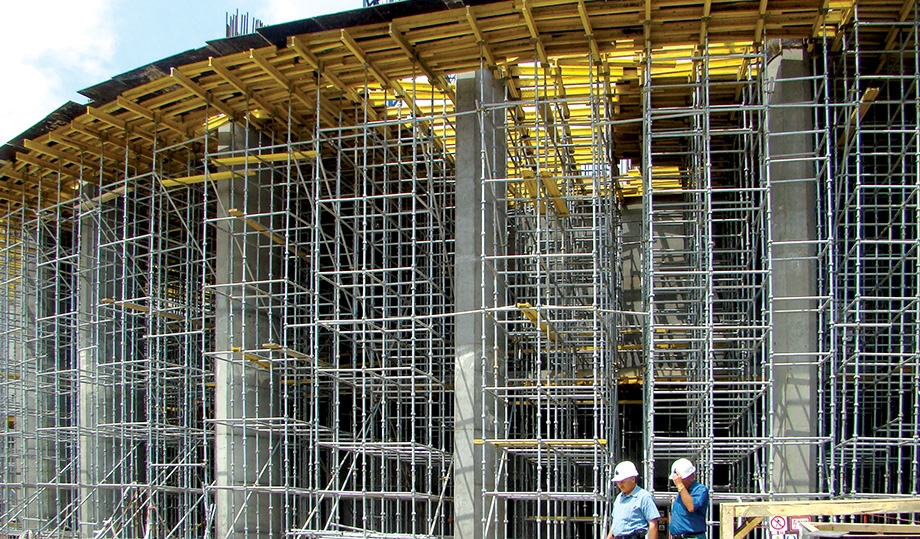
The CUP-LOCK slab formwork system (also known as Cup Lock or Cuplok) is designed to support formwork elements during the concreting of monolithic reinforced concrete structures, including both horizontal and inclined surfaces.
It is widely used in the construction of buildings, bridges, and tunnels, providing a stable and reliable load-bearing framework for slab and deck formwork operations.
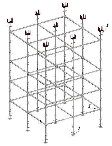
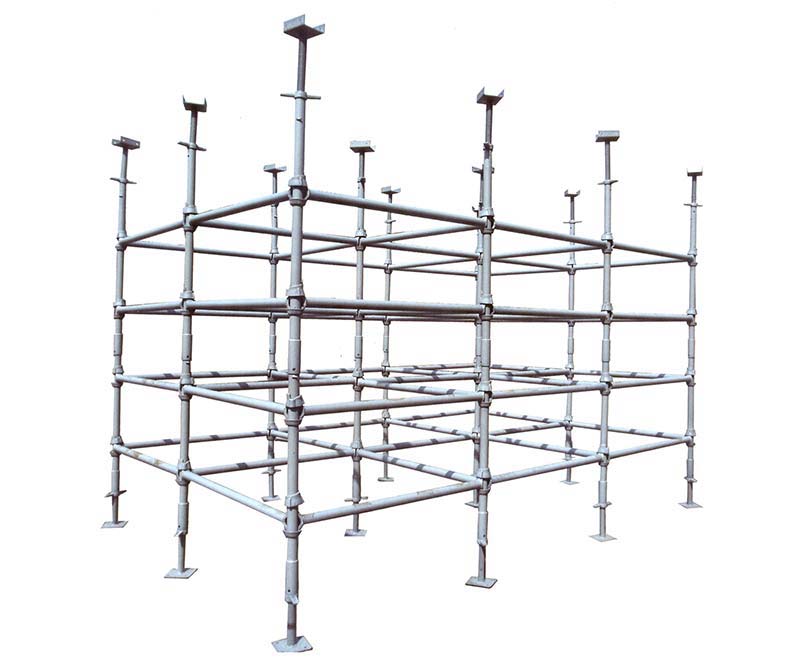
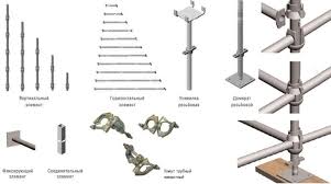
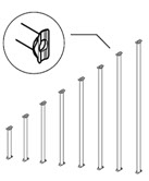
The load-bearing frame of this type of CUP-LOCK volumetric shoring system is a steel structure composed of vertical standards (No. 1) with heights ranging from 0.5 m to 3 m, and horizontal ledgers (No. 2) with lengths ranging from 0.5 m to 2 m.
The connection between the standards and horizontal ledgers is achieved using special cup-lock connectors, which, when locked, provide high precision and rigidity of the entire structure.

Vertical extension of the standards is carried out using connecting inserts (No. 5).
For precise height adjustment during the installation of timber formwork beams, adjustable screw jacks (No. 3) and adjustable U-heads (No. 4) are used.
Depending on the design load, the standards are manufactured with different spacing of the cup-lock connectors.
Standards are available with cup spacing of 0.5 / 0.6 / 0.75 / 1.0 meters.
The smaller the spacing, the greater the load-bearing capacity of the structure.

Assembly and Dismantling
The assembly and dismantling of scaffolding must be carried out under the supervision of a responsible site supervisor, who must:
-
Study the scaffold structure in detail.
-
Prepare a layout plan for the installation of the scaffolding specific to the project site.
-
Prepare a list of all necessary components and elements required for assembly.

Assembly Procedure
On a prepared surface, install the cup-lock standards, setting the lower rows of standards on adjustable base jacks.
While keeping the standards in a vertical position, connect them with horizontal ledgers (No. 2) as shown in the diagram.
To do this:
-
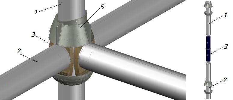
Raise the wedge nut (No. 5) and fix it in the upper position using the retaining clip.
-
Insert the flange of the horizontal ledger into the lower cup (No. 4) (each cup can accommodate up to four ledgers).
-
Lower the wedge nut until it rests against the ledger flange, then strike the nut with a hammer to turn it clockwise, ensuring a tight and secure fit of the ledger flange within the lock.
The cup-lock standards of the next tiers are connected to the lower standards using a spigot joint through the connecting insert (No. 3).
When assembling scaffolding above 3 meters, working platforms must be used, placed on horizontal ledgers at the required level.
Repeat these operations until the desired scaffold height is reached.
Dismantling must be carried out in the reverse order of assembly.
Cup-Lock Scaffolding System
Cup-Lock is the most popular scaffolding system in the world.
It is a multifunctional access and support system designed to provide complete working access and support for vertical loads.
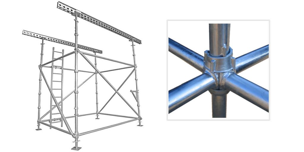
The main feature of the Cup-Lock system is its unique spherical node connection, which allows up to four horizontal ledgers to be attached to a single vertical standard at one locking point.
This innovative connection design makes the system one of the fastest and safest scaffolding solutions available.
Versatility and Applications
The comprehensive range of Cup-Lock components makes it suitable for creating a wide variety of access and support structures, including:
Thanks to its rigid connection nodes, there is no need for additional bracing, allowing the assembly of stable, continuous working platforms.
Cup-Lock scaffolding is manufactured in compliance with strict quality standards, with technical control and inspection performed at every stage of production.
Advantages of the Cup-Lock System
-
Faster and simpler assembly compared to traditional scaffolding systems.
-
Unique spherical node connection.
-
High resistance to mechanical stress and deformation.
-
Span length up to 3 meters.


Cup-Lock Scaffolding System
Connection Principle
The Cup-Lock connection points feature a unique spherical node design that allows up to four components to be joined simultaneously — using only a hammer.
Each node consists of two cup-shaped clamps:
-
A fixed lower cup, welded to the vertical standard at 500 mm intervals, and
-
A movable upper cup, which can rotate freely.
The metal ends of the horizontal ledgers and transoms are inserted into the lower cups, after which the upper cup is lowered and tightened.
This cup locking mechanism secures the components firmly in place — only a few hammer strikes on the edges of the upper cup are needed.
The connection and fastening of vertical and horizontal elements are achieved without bolts, nuts, or other consumable fasteners.
This design eliminates the risk of losing small parts when transporting the system between job sites, making Cup-Lock a truly unique and reliable system.
Material and Load Capacity
Cup-Lock components are made of high-strength steel.
The main load-bearing profile is a steel tube with a diameter of 48 mm and a wall thickness of 3 mm.
This simple yet robust system of standards, ledgers, transoms, cross braces, and adjustable base and head jacks provides a maximum load capacity of up to 74 kN (7,546 kg) per standard.
Such performance ensures outstanding reliability, economic efficiency, and reduced costs for transportation, assembly, and maintenance.
Applications of the Cup-Lock System
The wide range of Cup-Lock components allows the system to be used for almost any type of construction or support structure.
In most cases, the main elements are used in full, while only a few additional parts are needed to adjust the configuration on site.
Unlike other systems, Cup-Lock components are permanently welded to the standards, eliminating the loss of small parts during transportation — saving both time and money.
Decades of global experience in all types of construction projects have demonstrated the absolute reliability of the Cup-Lock system.
The system’s technical and structural design is supported by engineering software tools that ensure precise load calculation and configuration.
Cup-Lock was developed as a universal modular system, primarily focused on support structures for slabs, decks, and spans.
It is widely used in the construction of all types of bridges, including angled and arched structures.
The variety of cross and longitudinal braces available allows for an economical design of support frameworks for any slab thickness.
The combination of standards and adjustable jacks enables the system to accommodate any required working height.
Due to low point loads, Cup-Lock towers can be installed even on soft ground, stabilized only with base plates or panels.
Facade and Industrial Applications
Cup-Lock is also a reliable solution for facade scaffolding of various layouts and heights.
For these applications, the system uses external and internal lifting brackets, as well as working decks and platforms.
The circular node connections are particularly beneficial for arched or curved horizontal structures, making Cup-Lock highly valued in the chemical and oil industries.
Unlike many other systems, longitudinal members can be attached to the node at an angle, allowing them to adapt to any radius or curve without requiring special tube elements or custom fittings.
The horizontal projection of such structures can be configured as rectangles or trapezoids, depending on site geometry.
With its high load-bearing capacity and structural stability, the Cup-Lock system is suitable for a wide range of industrial and technological applications.
Horizontal ledgers can be installed 500 mm and 1,000 mm above the working platform, serving as guardrails and safety barriers.
Use of Cup-Lock as Independent Mobile Towers
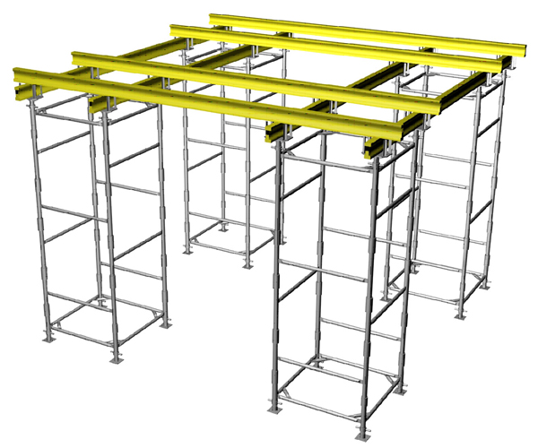
Thanks to its robust and self-supporting design, the Cup-Lock volumetric tower can also be used as independent mobile towers without additional horizontal bracing.
Such configurations are typically applied for slab heights from 4.5 to 5.5 meters and slab thicknesses up to 300 mm.
Cup-Lock towers measuring 1.5 × 1.5 m are installed at 1.7 m intervals, with each tower designed to support 10 m² of slab area.
When arranging Cup-Lock towers in this configuration, two key factors must be taken into account:
-
Risk of horizontal displacement during the concreting of the slab.
In this case, the concrete should be distributed as evenly as possible across the slab area, avoiding the accumulation of excessive weight in any single section.
-
Use of plywood–timber beams that meet technical specifications (TU), or alternatively, reinforced beams should be applied.
To minimize risks and ensure a rigid, integrated structure, horizontal braces of 1.7 m length can be used on the upper and middle tiers.