| Image |
Name, characteristics |
Units of measurement |
Weight (kg) |
Price |
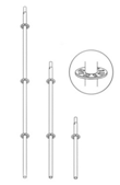 |
Flanged rack 3.0 m (6 flanges, 0.5 m spacing) |
pcs. |
10 |
|
2.5m Flanged Rack
(5 flanges, 0.5m spacing) |
pcs. |
8,5 |
|
2.0m Flanged Rack
(4 flanges, 0.5m spacing) |
pcs. |
6,8 |
|
| Flanged rack 1.5 m (3 flanges, 0.5 m spacing) |
pcs. |
5,5 |
|
Flanged rack » 1.0 m
(2 flanges, 0.5 m spacing) |
pcs. |
4,1 |
|
| Flanged post 0.5 m (1 flange, 0.5 m pitch) |
pcs. |
2,6 |
|
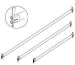 |
Horizontal crossbar 3,0m; |
pcs. |
7,2 |
|
| Horizontal crossbar 2,5m; |
pcs. |
6,1 |
|
| Horizontal crossbar 2,0m; |
pcs. |
4,9 |
|
| Horizontal crossbar 1,5m; |
pcs. |
3,8 |
|
| Horizontal crossbar 1,0m; |
pcs. |
2,7 |
|
| Horizontal crossbar 0,75m; |
pcs. |
2,1 |
|
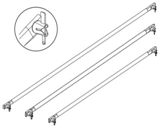 |
Diagonal crossbar 3,0х2,0m; |
pcs. |
6,3 |
|
| Diagonal crossbar 2,5х2,0m; |
pcs. |
5,7 |
|
| Diagonal crossbar 2,0х2,0m; |
pcs. |
5,2 |
|
| Diagonal crossbar 1,5х2,0m; |
pcs. |
4,7 |
|
| Diagonal crossbar 1,0х2,0m; |
pcs. |
4,3 |
|
| Diagonal crossbar 0,75х2,0m; |
pcs. |
4 |
|
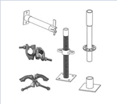
| Components for wedge scaffolding |
|


|
Starting element 0.3m |
pcs. |
1,9 |
|
| Wall stop for wedge scaffolding 0,3m |
pcs. |
1,8 |
|
| Wall stop for wedge scaffolding 0,4m |
pcs. |
2 |
|
| Wall stop for wedge scaffolding 0,5m |
pcs. |
2,3 |
|
| Installation support 48mm |
pcs. |
0,9 |
|
| Adjustable support 0,35м (Ø38) |
pcs. |
2,95 |
|
| Blind clamp |
pcs. |
1,1 |
|
| Rotary clamp |
pcs. |
1,2 |
|
| Metal flooring 3,00х0,31m |
pcs. |
24,8 |
|
| Metal flooring 2,50х0,31m |
pcs. |
20,7 |
|
| Metal flooring 2,00х0,31m |
pcs. |
16,5 |
|
| Metal flooring 1,50х0,31m |
pcs. |
12,4 |
|
| Flight of stairs 3,0х2,0/0,41m (1 site) |
pcs. |
30 |
|
| Flight of stairs 2,5х2,0/0,41m (1 site) |
pcs. |
26,5 |
|
| Flight of stairs 2,0х2,0/0,41m (1 site) |
pcs. |
23 |
|
| Hanging ladder 2,0m |
pcs. |
10,2 |
|
| Stairs (inclined) 2.5m railing |
pcs. |
|
|
| Inclined staircase 2.5 m |
pcs. |
|
|
| Fencing of the work site 3,0х1,0m |
pcs. |
15,5 |
|
| Fencing of the work site 2,5х1,0m |
pcs. |
12,7 |
|
| Fencing of the work site 2,0х1,0m |
pcs. |
10 |
|
| Fencing of the work site 1,5х1,0m |
pcs. |
8,4 |
|