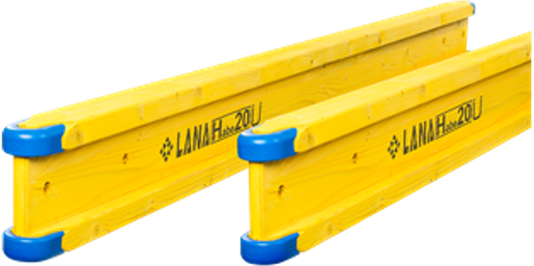


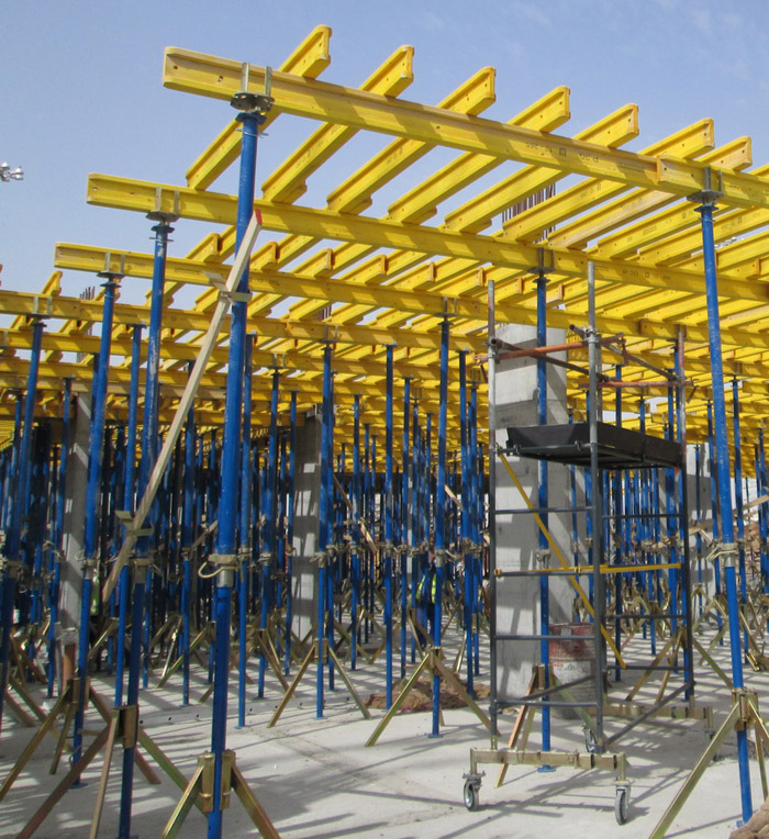
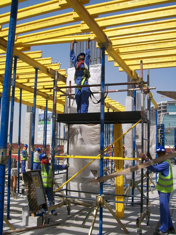
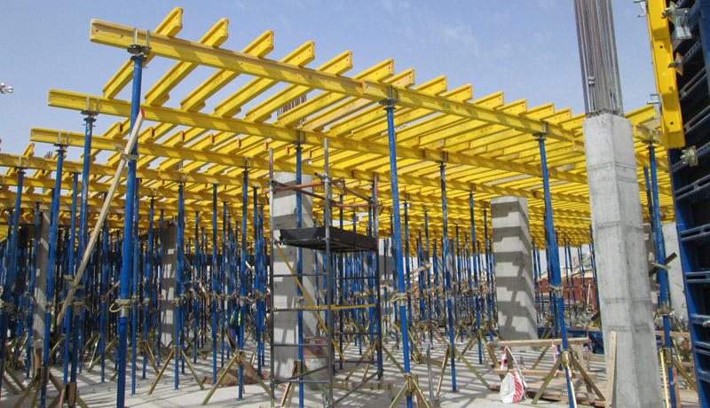


Step 4. Lay the transverse formwork beams.
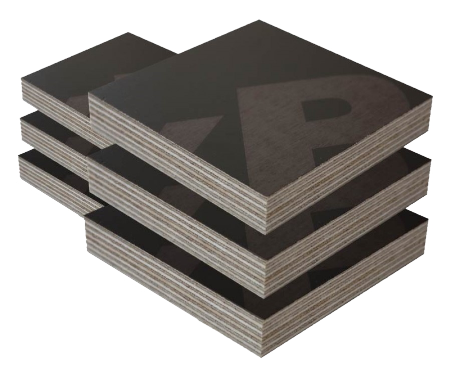
Place the formwork panels (decking).
Important instructions
For the safe use of our products, all applicable safety and occupational health regulations must be observed.
The illustrations shown in this manual may depict intermediate assembly stages and are therefore not always compliant with safety standards.
Before use, inspect all materials for quality. Any parts that are damaged, deformed, or weakened due to wear, corrosion, or decay must be discarded.
Only original spare parts should be used.
Mixing our formwork systems with those of other manufacturers is dangerous and requires special technical verification.
If necessary, we can send a field installation supervisor to your construction site to provide technical assistance.
Sequence for dismantling horizontal formwork
-
Remove all intermediate props.
-
Using a hammer, knock out the wedge of the drop head (it should lower by 6 cm).
-
Rotate and remove the transverse formwork beams (the beams located under the plywood joints remain in place).
-
Remove the plywood.
-
Dismantle the transverse and longitudinal beams.
-
Remove the drop heads, take down the props, and remove the tripods.
Why are supporting props needed after formwork removal?
Depending on the construction process, temporary supporting props may be required to absorb the loads caused by the settling of fresh concrete or the weight of upper floor concreting.
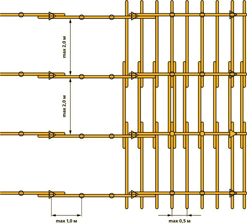
Correct placement of supporting props
The function of these props is to distribute the loads between the freshly cast slab and the slab below it.
The loads depend on the relative stiffness of the two slabs.
Recommended ratios for auxiliary props to formwork props:
-
0.4 auxiliary props per formwork prop, if both slabs have similar stiffness.
-
0.8 auxiliary props per formwork prop, if the lower slab is significantly stiffer (e.g., foundation slabs).
Consult a specialist
As a general rule, regardless of the above recommendations, the issue of auxiliary supports should always be discussed with qualified structural engineers.
In uncertain cases — especially for heterogeneous slab systems — consult the engineer who performed the static calculations.
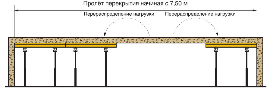
Main rule
The formwork removal process should generally begin from the center of the slab (span) and proceed toward the edges.
For large spans, this rule is mandatory.
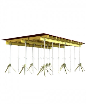
Elements of slab formwork
|
|
|
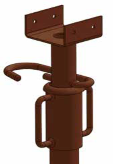
End - shutter support for slab
Extension for beam forming support
|